


InCadPRO: The design of Inim systems takes shape directly from your CAD software
- calendar_today September 2, 2026
- labelProduct Release

Designing a security system involves managing schematic diagrams, devices, identifiers, quantities, diagrams, and technical documentation.
A new tool, within the same work environment
InCadPRO was developed to integrate with CAD platforms such as AutoCAD and ZWCAD. Supported versions: Autodesk, AutoCAD Full, ZWCAD, ZWCAD Professional.
Its purpose is not to replace the tools already used by designers and installers, but to enhance them with features specifically designed for designing Inim systems.
Using a dedicated toolbar, professionals can add devices, identify them, generate diagrams, calculate quantities, and export data—all while continuing to work within their usual workflow.
This reduces the need to constantly switch between different software programs and ensures greater consistency between the graphics, documentation, and system configuration.

How InCadPRO Works
The plug-in works in a linear process: it starts with a CAD drawing and results in a more structured design, complete with diagrams, quantities, and exportable data.
1. The project is based on the Inim legends
The first feature provided by InCadPRO is a custom legend that includes the devices associated with the systems:
FIRE AND GAS DETECTION;
EVAC AND SOUND DIFFUSION;
VISUAL AND AUDIBLE ALARM;
INTRUSION DETECTION
The legend serves as the foundation of the project and allows devices to be placed according to consistent and standardized graphic criteria.
Installing the devices directly into the board
Label: Every device becomes part of the project
Once inserted into the drawing, devices can be identified using the Label command. Each element is assigned a unique address or identifier. Labeling creates a clear relationship between the graphic symbol and the device’s technical information. This step is essential because it allows InCadPRO to interpret the elements in the drawing and use them to automatically generate system diagrams. The CAD drawing is therefore no longer just a collection of symbols; it becomes an organized database of technical information.
Automatic diagrams for a clearer view of the system
Fire Diagrams
For Fire systems, three representations are available:
Displays individual devices, along with their assigned addresses and corresponding connections.
Provides an overview of the devices on the loop and the general system architecture.
Cumulative Groups devices by category and displays the total quantities, providing a summary view of the system.
EVAC Diagrams
Two display modes are available for EVAC systems:
Displays individual devices, along with their assigned addresses and corresponding connections.
Provides an overview of the devices on the loop and the general system architecture.
The diagrams also show the power consumption of each amplifier, broken down by Line A and Line B. This provides the designer with immediately readable information for analyzing and documenting the system.
Intrusion Diagrams
For the "Intrusione" section, there is only one representation available:
Displays individual devices, along with their assigned addresses and corresponding connections.
In this case, proper application of labels ensures a well-organized representation of the Inim- Security & Comfort devices and keeps the schematic diagram and technical documentation aligned.
Symbols, quantities, and legends—always under control
InCadPRO also includes a series of functions designed to simplify the tasks that follow the creation of the panel. The “Convert Symbols” command allows you to switch from Inim’s proprietary graphics to the UNI graphics standard. The “Count Device Quantities,” “Reset Device Quantities,” and “Calculate Cable Length” commands, on the other hand, allow you to quickly calculate the number of devices in the drawing and, when necessary, reset the count to perform it again. Meanwhile, the “Calculate Cable Length” command automatically calculates the number of meters of cable required and finalizes the project. With the “Create Legend” command, the plug-in generates a legend consisting solely of the devices actually used in the project. This allows you to replace the complete legend with a more concise and relevant version, improving the readability of the final document.
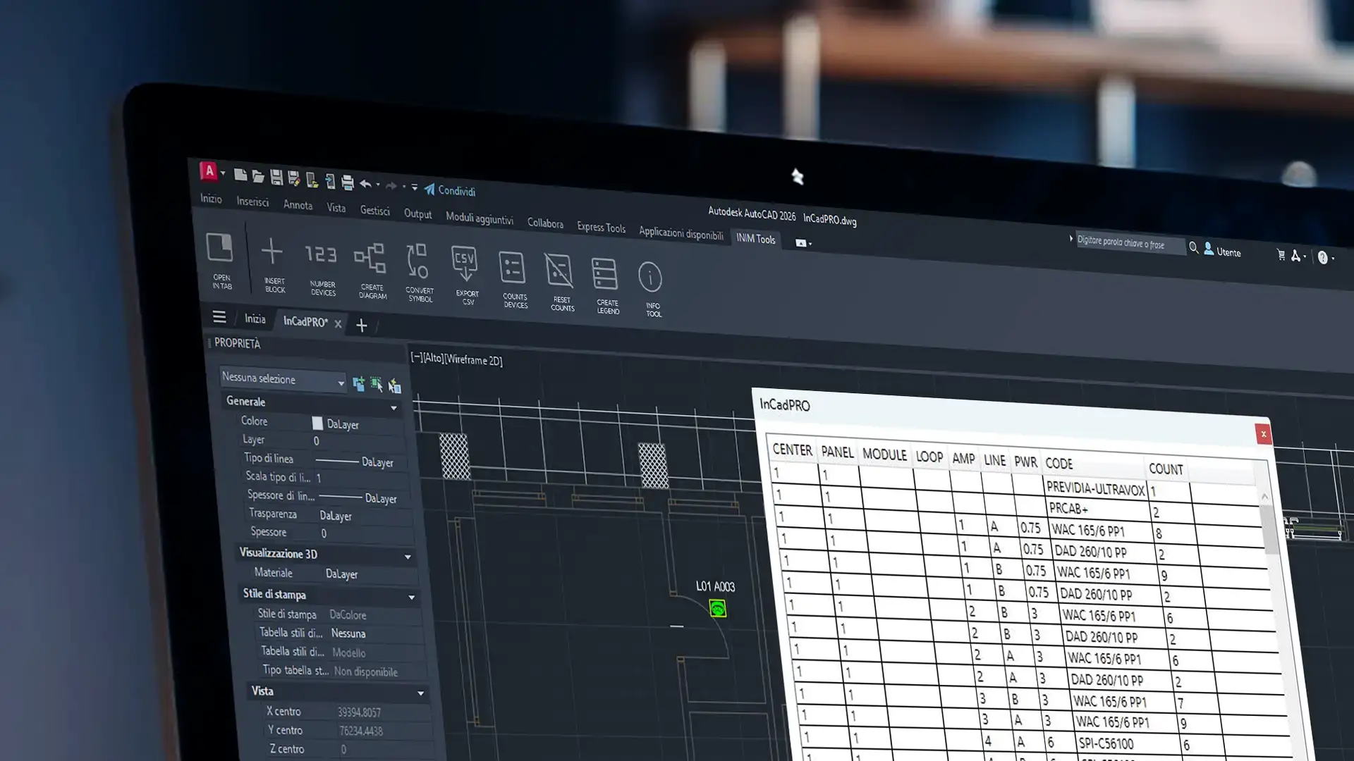
From CAD drawings to project data
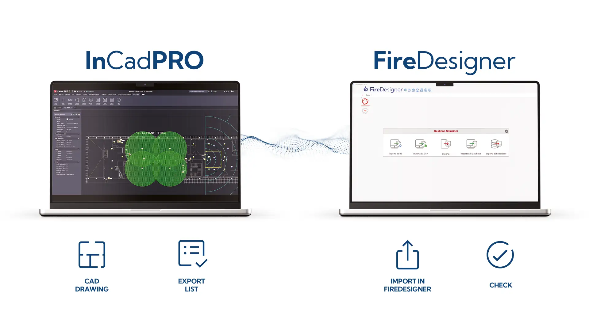
The integration with FireDesigner takes design to the next level!
InCadPRO takes the project beyond CAD design.
By using the dedicated export function and then importing the data into FireDesigner, you can view the devices entered and their quantities, verify the power consumption calculations, and check for any errors or omissions.
The workflow can be summarized in a few steps:
CAD drawing -> inserting devices -> labels -> diagrams -> quantities -> export -> verification in FireDesigner.
InCadPRO thus creates a functional link between graphic design, technical data, and system verification, enhancing the entire Inim ecosystem.
Activation and Updates
After installation on the computer, InCadPRO requires an activation process. The professional must have an active account on the Inim website and can request activation directly from the plug-in or using a key provided by their sales representative.
Once the procedure is complete, the tool becomes fully operational.
The "Update" command also allows you to download software, data, and content updates on your own, including new features that will be introduced over time.
Who is InCadPRO designed for?
InCadPRO is primarily intended for designers, engineering firms, and installers who work with Inim systems and routinely use CAD software.
The plug-in addresses specific needs:
- reduce repetitive tasks;
- better organize systems and information;
- ensure consistency between tables, diagrams, and documentation;
- get results faster;
- transfer the data to the next phases of the project;
- work without leaving your CAD environment.
A simpler, more structured design process
InCadPRO brings the tools for designing Inim systems directly into the CAD software you use every day.
Legends, devices, labels, diagrams, counts, and exports all become part of a single process, designed to guide professionals from the initial entry into the drawing through to technical verification.
An approach that makes the project more organized, the information easier to reuse, and the work more consistent at every stage.